
VLANs are commonly used to segment a network into separate logical networks while allowing multiple networks to share the same physical infrastructure.
In this step-by-step tutorial, we’ll configure two VLANs on a FortiGate: a Users VLAN and a Servers VLAN. The FortiGate will provide Layer 3 connectivity and DHCP services for both VLANs, while a Layer 2 switch will carry the VLANs over an 802.1Q trunk.
We’ll also configure FortiGate firewall policies to control traffic between the VLANs and provide Internet access to the Users network.
Topology#
The lab uses a FortiGate connected to the Internet through port1 (WAN) and to a Layer 2 switch through port2. The switch-to-FortiGate connection is configured as an 802.1Q trunk carrying both VLANs.
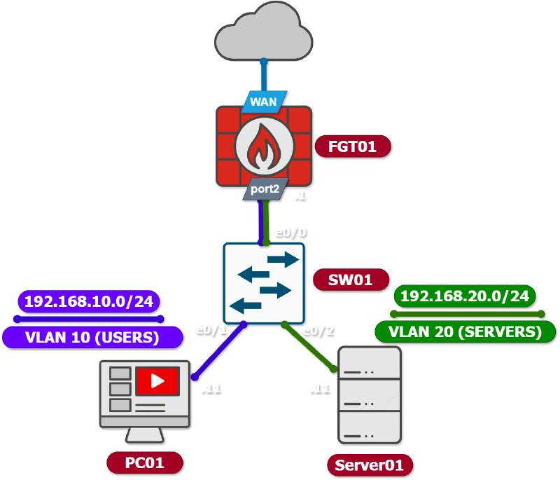
The endpoint connections are configured as access ports:
Ethernet0/1→ VLAN 10Ethernet0/2→ VLAN 20
We’ll configure FortiGate port2 with two VLAN subinterfaces according to our topology:
| VLAN | Name | Subnet | Gateway | Purpose |
|---|---|---|---|---|
| 10 | USERS | 192.168.10.0/24 | 192.168.10.1 | User network |
| 20 | SERVERS | 192.168.20.0/24 | 192.168.20.1 | Server network |
This design allows both networks to use the same physical switch while maintaining logical separation between users and servers. The FortiGate acts as the default gateway for both VLANs and controls traffic between them using firewall policies.
FortiGate VLAN Configuration#
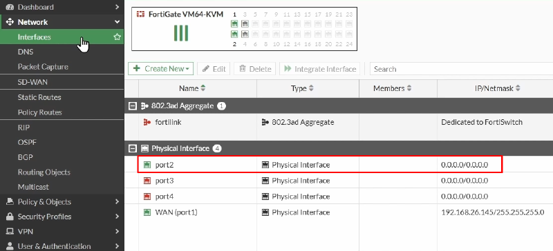
On the FortiGate, go to Network > Interfaces
The WAN interface, port1, is already configured and will be used for Internet connectivity.
The VLAN interfaces will be created on port2.
Creating the Users VLAN#
Click Create New > Interface.
Configure the interface with the following settings:
| Setting | Value |
|---|---|
| Name | VLAN10 |
| Alias | USERS |
| Type | VLAN |
| VLAN Protocol | 802.1Q |
| Interface | port2 |
| VLAN ID | 10 |
| Role | LAN |
| IP/Netmask | 192.168.10.1/24 |
| Administrative Access (IPv4) | PING |
Under IPv4 Administrative Access, enable PING. This allows us to test connectivity between the client and the FortiGate VLAN interface.
Enable DHCP Server and configure:
| Setting | Value |
|---|---|
| Address Range | 192.168.10.11 - 192.168.10.99 |
| Netmask | 255.255.255.0 |
| Default Gateway | Same as Interface IP |
| DNS Server | Same as System DNS |
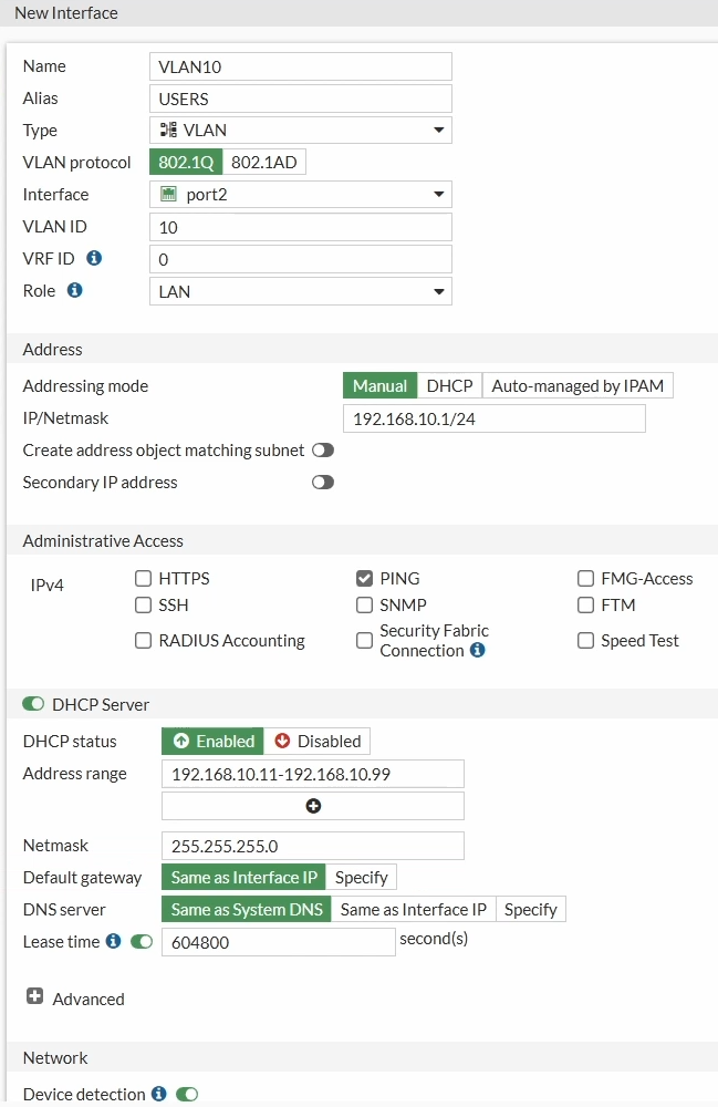
Click OK to create the VLAN interface.
The FortiGate is now configured to provide both Layer 3 connectivity and DHCP services for VLAN 10.
Creating the Servers VLAN#
Create another interface by selecting. Create New > Interface
Configure the second VLAN as follows:
| Setting | Value |
|---|---|
| Name | VLAN20 |
| Alias | SERVERS |
| Type | VLAN |
| VLAN Protocol | 802.1Q |
| Interface | port2 |
| VLAN ID | 20 |
| Role | LAN |
| IP/Netmask | 192.168.20.1/24 |
| Administrative Access (IPv4) | PING |
Enable the DHCP server with:
| Setting | Value |
|---|---|
| Address Range | 192.168.20.11 - 192.168.20.99 |
| Netmask | 255.255.255.0 |
| Default Gateway | Same as Interface IP |
| DNS Server | Same as System DNS |
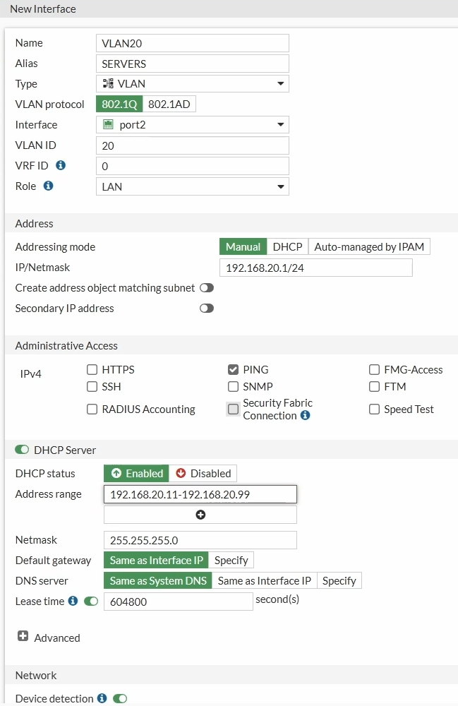
Click OK.
At this point, the FortiGate has two VLAN subinterfaces configured on the same physical interface:
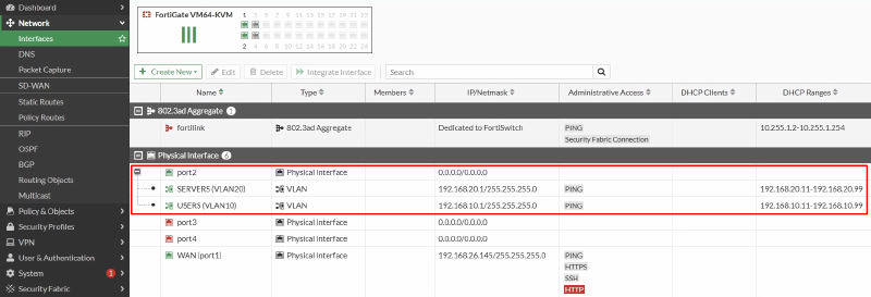
The corresponding DHCP scopes are also enabled on both interfaces.
Checking the Switch Configuration#
The Layer 2 switch is already configured in this lab, so we only need to review the relevant ports.
The connection toward the FortiGate is configured as an 802.1Q trunk:
interface Ethernet0/0
 switchport trunk encapsulation dot1q
 switchport trunk allowed vlan 10,20
 switchport mode trunk
The PC connection is an access port in VLAN 10:
interface Ethernet0/1
 switchport access vlan 10
 switchport mode access
The Server connection is an access port in VLAN 20:
interface Ethernet0/2
 switchport access vlan 20
 switchport mode access
Therefore, the switch performs two important functions:
- It carries VLAN 10 and VLAN 20 between the switch and FortiGate using the trunk.
- It places each endpoint into the appropriate access VLAN.
This configuration corresponds to the switch topology used in the lab.
Testing VLAN Connectivity#
Now that the FortiGate and switch configuration are complete, we can test the network step by step.
Test 1: Default Gateway Connectivity#
The first test verifies that each endpoint can communicate with its FortiGate default gateway.
PC01 (Linux):
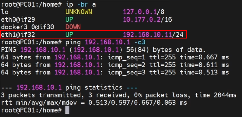
- On PC01, check the current IP configuration:
ip -br a- PC01 should have received an IP address from the VLAN 10 DHCP server. For example:
192.168.10.11/24 - Now ping the FortiGate VLAN 10 interface:
ping 192.168.10.1 -c3- The ping should succeed.
- This confirms that PC01 can communicate with the FortiGate through VLAN 10.
Server01 (Linux):
- On Server01, check its IP configuration:
ip -br a- The server should have received an address from the VLAN 20 DHCP scope, e.g.
192.168.20.11/24 - Then test its default gateway:
ping 192.168.20.1 -c3- The ping should also succeed.
- At this point, both VLANs are working correctly between their endpoints and the FortiGate.

Test 2: Internet Connectivity#
Next, we’ll test Internet connectivity from the Users VLAN.
First, verify PC01’s routing table:
ip routeThe default route should point to the FortiGate VLAN 10 interface: 192.168.10.1
Now test connectivity to Google’s public DNS server:
ping 8.8.8.8 -c3Initially, the ping will fail.
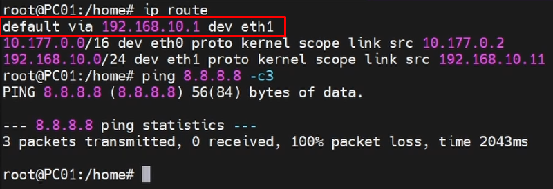
The VLAN interface and routing are working, but FortiGate does not allow traffic through the firewall unless an appropriate firewall policy exists.
Creating the Users-to-WAN Firewall Policy:
On the FortiGate, go to: Policy & Objects > Firewall Policy
Click Create New. Configure the policy as follows:
| Setting | Value |
|---|---|
| Name | USERS_to_WAN |
| Incoming Interface | USERS |
| Outgoing Interface | WAN |
| Source | USERS_Subnet |
| Destination | all |
| Service | ALL |
| Action | ACCEPT |
| NAT | Enabled |
| Log Allowed Traffic | All Sessions |
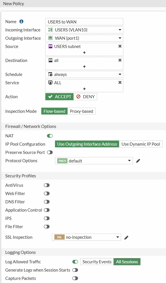
For the source address, create a new address object:
| Setting | Value |
|---|---|
| Name | USERS_Subnet |
| IP/Netmask | 192.168.10.0/24 |
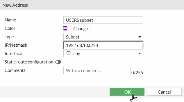
Click OK and save the firewall policy.
The policy allows traffic originating from the Users subnet to leave through the WAN interface, with source NAT enabled.
Now return to PC01 and repeat the test:
ping 8.8.8.8 -c3This time, the ping should succeed.
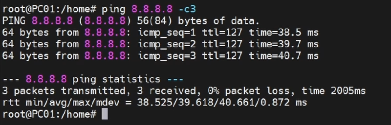
We now have Internet connectivity from VLAN 10.
Checking the Traffic Logs:
The traffic can also be verified directly on the FortiGate.
Go to: Log & Report > Forward Traffic
The traffic generated by PC01 should appear in the logs, allowing you to verify that it matched the USERS_to_WAN firewall policy.

Test 3: Inter-VLAN Connectivity#
The final test verifies communication between VLAN 10 and VLAN 20.
Before creating a firewall policy, let’s check the FortiGate routing table.
Go to Dashboard > Network > Routing:
The FortiGate should show both VLAN subnets as directly connected:
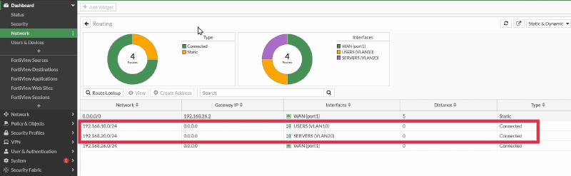
This means that FortiGate already knows how to route traffic between the two networks.
However, having a route does not automatically mean that traffic will be allowed. FortiGate firewall policies determine whether the traffic is permitted.
Creating the Inter-VLAN Firewall Policy:
On the FortiGate, go to: Policy & Objects > Firewall Policy
Click Create New.
Configure the policy as follows:
| Setting | Value |
|---|---|
| Name | USERS_to_SERVERS_Ping |
| Incoming Interface | USERS |
| Outgoing Interface | SERVERS |
| Source | USERS_Subnet |
| Destination | SERVERS_Subnet |
| Service | PING |
| Action | ACCEPT |
| NAT | Disabled |
| Log Allowed Traffic | All Sessions |
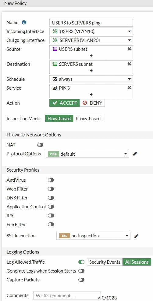
For the destination, create a new address object:
| Setting | Value |
|---|---|
| Name | SERVERS_Subnet |
| IP/Netmask | 192.168.20.0/24 |
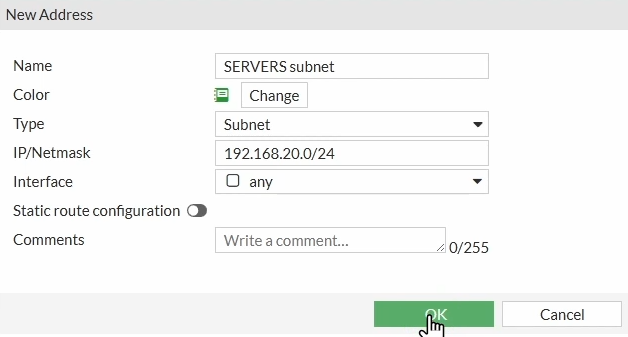
Select this address object as the destination.
For this example, the service is limited to PING. This is important because the policy does not provide unrestricted access between the two networks.
NAT should remain disabled because this is traffic between two internal networks.
Now return to PC01 and try to ping the server:
ping 192.168.20.11 -c3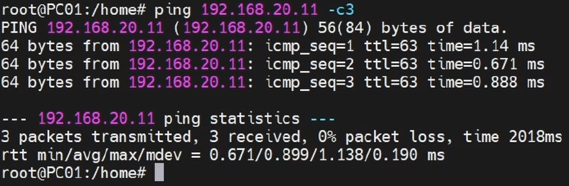
PC01 can communicate with Server01 across the two different VLANs.
Checking the Inter-VLAN Traffic Logs:
As with the Internet test, you can verify the connection on the FortiGate.
Go to: Log & Report > Forward Traffic

The traffic between the Users and Servers networks should appear in the logs and show that it was allowed by the USERS_to_SERVERS_Ping policy.